Non-running dynos and laser valve tracking
 In previous issues of RET-Monitor under this keyword, the focus has been on dynamometer systems designed for measuring running engines. This month the focus will be on systems that do not operate on a running engine, and specifically their use for monitoring movement in reciprocating components using laser measurement systems.
The use of lasers to measure the movement of the valvetrain and other components is fairly well documented, however a brief summary is beneficial. In essence, a large electric motor is used to spin an engine through its operating rpm range, while a laser beam is used to measure factors such as valve lift and rocker arm deflection.
The main system available on the market uses a single laser to achieve these measurements, but one particular NASCAR engine operation found this set-up to be insufficient for its needs. The specific areas the company wanted to study were valve movement, in order to validate its simulation models, and piston rock, to identify areas for improvement in piston skirt design.
In particular the engineers found that the resolution provided by the single laser, which was accurate to 20 microns, was too low. The solution was to replace the single laser with a twin array, with each of the new lasers accurate to 10 microns. For the valvetrain testing, the twin laser array was directed through a cutaway section of cylinder block at the inlet and exhaust valves, which were covered with a thin film of retro reflective tape to improve the strength of the return signal.
A baseline reading for valve movement was taken at 3000 rpm, which allowed an accurate trace of the valve movement to be created and where factors such as bounce on closing would not be present. With a baseline established, reading could then be taken at high rpm, up to the 9000 rpm redline, to obtain an accurate record of the influence of valve spring harmonics, as well as identifying any undesired traits such as valve 'loft' or 'bounce' on closing. The end result was that potential problems, which would not usually become apparent until component damage occurred, could be addressed, and the process is now used to validate new valvetrain designs.
The second area to be investigated was piston rock, a particularly relevant issue in NASCAR Cup engines, where generous piston clearances are the norm (in the region of 0.010 in). The same twin laser array was used, although here the cylinder head was removed to allow access to the piston crown. Retro reflective tape again helped to improve the strength of the return signal. The lasers were pointed at opposite sides of the piston crown, and the engine cycled through its operating rpm range.
While undertaking this testing it was found that oil mist from the crankcase degraded signal strength; the solution was to use a fume extractor nozzle placed close to the bore. As a result of this testing cycle, the degree of piston rock could be accurately assessed at each stage of the crank's rotation, providing data that allowed the piston skirt design to be modified in order to reduce frictional losses.
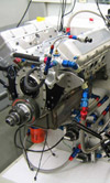
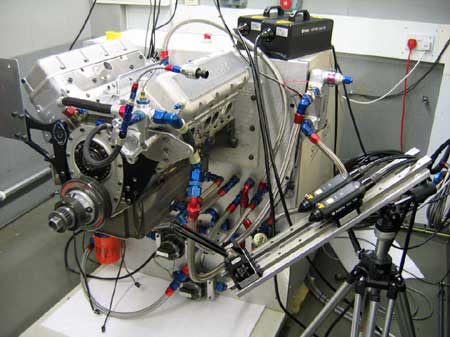
Fig. 1 - The twin laser array used for measuring valve and piston movement
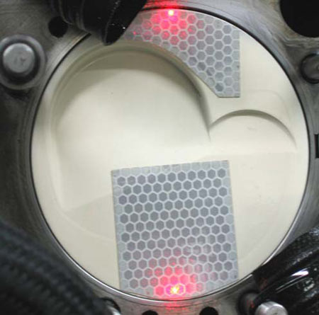
Fig. 2 - Retro reflective tape was used to aid return signal strength for the lasers
Written by Lawrence Butcher
3207