Obtaining greater elastic deformation in a multi-layer steel gasket by adding a stopper element
There are some engines, mainly from the past, that have major components integrated into one part. There is of course the monobloc engine type, such as the De Dion-Bouton engine of 1905, which integrated cylinders and head into one machined casting, but in the modern world we find this type of highly integrated designs only in less powerful engines such as the Honda GC family, which combines the cylinder head, cylinder and half the crankcase, split at the crankshaft line.
Other than these, and mainly for manufacturing and serviceability reasons, the major engine parts are designed as we know them today, with separate components connected using bolts and sealed with one or more gaskets. As these designs became standard practice, the development of gasket materials started. Initially, the loading on the gaskets was rather low because of moderate power output and limited internal pressures, so gasket design was focused on sealing two or three mating components with only small machining defects, porosities and other imperfections. This is why early gaskets consisted of materials that yielded to some extent, enabling them to deform and fill those imperfections.
As engine temperatures and pressures increased though, these gaskets showed significant failure rates, typically leading to blown head gaskets and/or leaking exhaust manifolds. As early adopters of new concepts, Formula One engineers switched to copper or steel ring head gaskets, which showed to be a significant improvement for sealing the combustion chamber. Soon after that, these gaskets were introduced for production cars as well, where additionally, for ease of assembly, they became integrated into cylinder head gaskets.
Later, the head gasket material changed to single-layer steel. This was a major improvement over earlier materials, which often contained asbestos, a now forbidden material. Single-layer steel gaskets provide significant better mechanical strength as well as the ability to cope better with micro-movements of the mating surfaces. With earlier materials these movements could lead to gasket damage and possibly cracks in the gasket material.
As one of the later steps in the development, multi-layer steel (MLS) gaskets were introduced, with so-called ‘beads’ to increase local sealing capability. To get a feel for their dimensions, the bead shapes are typically up to about 0.4 mm high, depending on size and application, where the actual layer thickness is even less (about 0.25 mm). The top and bottom layers are often coated to reduce friction, in case micro-movements occur.
For exhausts in particular, given their extremely high temperatures, MLS gaskets have vastly improved the sealing capability, although the actual sealing geometry – as in the bead-deformed zones – remains the sensitive area of the gasket due to relaxation of the material under high temperatures.
The basis of an MLS gasket are multiple layers of steel, of which one or more layers have pressed beads, being positioned on top of each other. When the layers are being assembled and the bolts are being torqued, the beads deform, leading to elevated local pressures in the beads, the actual sealing location. These beads will deform partly plastic and partly elastic, meaning they can adapt to temperature and load fluctuations (as long as the fluctuations are not larger than the elastic compression of the bead).
What was occasionally seen however was that the beads were compressed more plastically than intended, reducing the remaining elasticity in the gasket beads, leading to too little reserve against temperature and load fluctuations. To improve this, a so-called ‘stopper’ layer was introduced. The thickness of this layer – which is also the third or middle layer of the MLS gasket – determines the amount of maximum deformation of the beads of the upper and lower layers, leading to better control over the elastic deformation of the beads. This can be controlled by the thickness of this middle layer.
If a further, more local optimisation of the bead deformation needs to be achieved, the stopper or middle layer can also be designed with a certain topography rather than just being flat. For example, it might be desirable that the beads have more elastic deformation between two bolts, giving a lower clamping load with increased bolt spacing.
In general there are no limits to how this stopper or middle layer can be shaped. That means a very homogeneous contact pressure distribution can be achieved, even with flat gaskets and significant bolt spans.
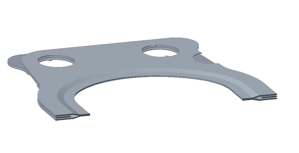 Fig. 1 - Multi-layer steel gasket with stopper element seen between the two outer layers
Written by Dieter van der Put
6304