One sensor, many uses
"So how much information can you get from one sensor" is a question that many will ask at some time or other. A temperature sensor for instance can provide data to the engine ECU to determine the degree of fuelling required. That same information can be used to set the engine idle speed as well as any cold/hot-start strategy, and at the same time be relayed to the driver by some kind of temperature gauge. A 'bigger bang for your buck' is one way of looking at it, much approved by those controlling the purse strings, but from an engineering perspective the reduced weight and sheer elegance of the design is the goal.
Likewise the Hall effect sensor can be used to detect the position of the crankshaft relative to the point of mixture ignition and, when counted over time, used to indicate the average rotational speed. Not only can this be used in the ignition and fuelling map, when added cumulatively the data can be useful in switching events or fuelling strategies. The transfer between initial cranking and cold-start fuelling strategies is perhaps an example of this.
One of the best and most ingenious examples of this approach, strangely enough also using a Hall effect device, is to be found on the latest mechanical flywheel energy storage device being used at Le Mans this year. The unit, as installed in an LM P1 car, is mounted between the engine and gearbox, and complete with all its ancillaries - hydraulic pumps, lube pumps, scavenge pumps, oil tank, vac pump and control valves - it weighs 37.9 kg
The control system, an in-house design, relies on two Hall effect high-speed sensors, and generates a huge amount of data. But if you imagine that all that is generated is rpm then think again.
Originally the energy-storing flywheel was connected to the driveline via a continuously variable transmission, or VCT. The latest version, however, is connected to the gearbox input shaft using a system of three gears clutched in and out. Using a six-speed gearbox this means 18 gear ratios between the engine input speed and the road wheel speed.
Considering the role of the two sensors, the designer offers this explanation. "The first measures the flywheel speed, and hence its energy content, while at the same time the rate of change of this is proportional to the power transmitted. If you know the speed and the power then the shaft torque can be calculated. At the other side of the clutch we have the other speed sensor, and since all three shafts are geared together we know how fast each is rotating and hence the speed difference across the clutch at any instant."
Knowing the energy in and that coming out gives an accurate indication of the energy dissipated through the clutch, and when mapped against the coolant flow rates and the heat transfer characteristics, the instantaneous clutch temperature can be derived. In theory, therefore, so long as this temperature is kept below a certain figure, the clutch controlling the energy flow in and out of the flywheel, will never burn out.
Not bad for a couple of inexpensive 'off-the-shelf' speed sensors as well as a lot of painstaking development.
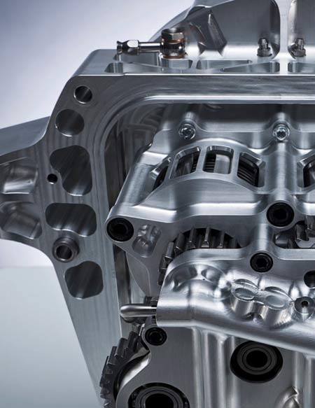
Fig. 1 - Energy storage using a clutched flywheel and a couple of simple sensors
Written by John Coxon