Split crankshafts
 The vast majority of race crankshafts that we see are made from one piece of material and are generally machined from either a billet of wrought steel, a forging or possibly a casting - certainly in the case of multi-cylinder engines this is the norm.
For a substantial proportion of certain types of engine, however, it is typical to find a crankshaft assembled from a number of pieces. This is generally the case where needle-roller bearings are used for the big-end bearing.
The types of engine that commonly use this method of construction are either single-cylinder four-stroke engines such as we find in motocross machinery, or two-stroke engines. Two-stroke engines find common use in motorcycle racing - although sadly even the 125 cc Grand Prix class is soon to disappear - and karting.
The crankshaft is assembled with the bearing and con rod in place on the crankpin, with the con rod being of the solid type with no split across the big end, allowing it to be clamped around the crankpin of a 'conventional' crankshaft.
In conventional two-stroke race engines, crankcase lubrication is looked after by oil that is either pre-mixed with the fuel or metered in some proportion to the fuel by a pump from a tank. After it has fulfilled its lubrication task, the oil passes into the combustion chamber where it is combusted with the fuel. Given the marginal lubrication, the needle roller is a natural choice for such engines.
Single-cylinder four-stroke engines can also dispense with a complicated crank oiling system by using the needle-roller big-end bearing. There is some evidence that needle-roller bearings can offer advantages in terms of friction, and in the V10 era some teams are known to have tested if not raced engines with needle-roller main bearings using ceramic rolling elements. This is borne out by the fact that the regulations were specifically altered a few years ago to outlaw ceramic bearing elements by mandating an iron-based alloy for rolling bearing elements.
The crankshaft for a single-cylinder engine can typically be made in two or three pieces. The two-piece crankshaft has one main bearing, a crank 'cheek' and the crankpin as a single piece, and a second piece which is a main bearing journal and a crank cheek. The crankpin is a heavy interference fit into the cheek of the second piece. A three-piece single-cylinder crank has a separate crankpin.

Multi-cylinder crankshafts can be assembled in this way and a great many two- and four-cylinder two-stroke engines were built like this.
Problems can arise in the incorrect alignment of the different pieces, causing strain on the crank when being fitted and excessive loads on the bearings. The depth of the press fit needs to be accurately controlled in order to prevent the con rod becoming trapped between the two crank 'halves'.
To be assembled correctly, proper tooling should be used. Furthermore, the amount of interference needs to be tightly controlled. Insufficient interference can see the assembly twist in use, and it is common to see racing cranks that have been welded to prevent this.
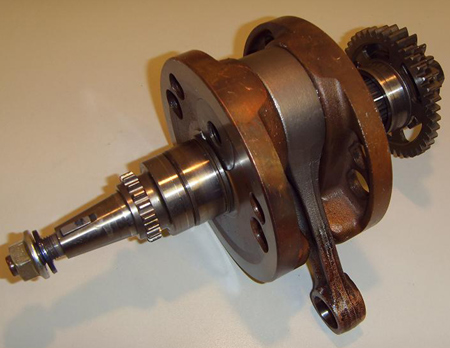
Fig. 1 - This crankshaft assembly from a four-stroke motocross machine has a split crankshaft and a single-piece con rod (Courtesy of TSRMX.co.uk)
Written by Wayne Ward