Twin injector blending
 Most of the time many of us are quite happy with just one injector per cylinder. The complexity of EFi arrangements and the software necessary to control an engine under the wide range of anticipated conditions are complex enough without going looking for problems.
But there are occasions when the one injector is not enough, say when the turndown ratio of any single injector is simply not large enough to cover the anticipated fuelling requirements of the engine. A typical example of this could be a supercharged/turbocharged unit with a fuel demand very similar to that of a naturally aspirated unit at low speeds and light throttle openings, whereas at high speed and rated boost this fuel demand could outstrip the flow capability of the injector.
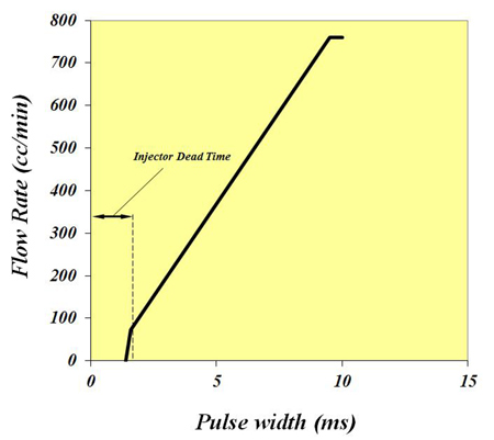
Since injectors tend to have a 'dead time' of about 1-1.5 milliseconds below which no fuel will flow, and are therefore far from linear at their lower operating flow rates, increasing the size of the injector to protect the engine at high speeds and loads will almost certainly give poor control in the low-speed part of the map. When a sensible compromise cannot be achieved using a single injector unit per cylinder, the added complexity of a twin-injector design will need to be tackled.
An obvious solution is to package the injectors side by side in roughly the same relative position to the intake valve as in a single-injector arrangement. While this might appear to be an elegant solution using the same fuel rail and minimising the Bill of Materials, the layout fails to take advantage of the possibilities of improved performance that could be obtained by mounting the secondary injector ring upstream of the first.
In particular, while the primary injector can be targeted at the back of the intake valves, the secondary set can be moved to the entry of the intake runner injecting centrally just in front of the intake bellmouth. Injecting at this latter position only when the engine is running at higher engine speed and large throttle openings ensures better vaporisation of the fuel and is accepted by many as the position for best overall engine power. At lower speeds, the primary grouping only should be used, as this will give better low-speed torque and transient throttle response - operating the secondary system at anything other than high intake air velocities might cause the fuel to drop out of the air stream, causing hesitation and possible flat spots.
The critical calibration zone, however, is in the transition zone when either the secondary (larger) group takes over or when they combine with the primary group at the higher intake air mass flow rate. Each time injectors are switched on after a period of inactivity, a variable enrichment strategy may need to be followed to compensate for the inevitable wall wetting on the inside of the manifold.
Furthermore, to prevent any possible oscillation between groups at the changeover point when the secondary system cuts in or out, the secondary system should always switch on somewhere at least 50 or even 100 rpm above the point where they switch off. By slashing the injector pulse width or cutting it immediately the secondary group tips in, and by compensating for the wall wetting effect, eventually (and after a lot of trial and error), a perfectly seamless transient calibration can be obtained.
It may take some time to refine but the result could even give a small overall increase in peak performance as well.
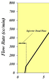
Fig. 1 - Injector flow characteristics
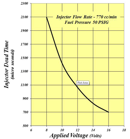
Fig. 2 - Variation of injector dead time with applied voltage
Written by John Coxon
4738