The air trumpet
It might seem difficult to believe but there was a time when not all engine designers believed in free-breathing engines. These days of course the key to the best possible engine performance is generally accepted as having the least restrictive intake system of a size and length to take advantage of the inevitable pressure pulsation within it. In the early days of engine design the preoccupation in packing the engine cylinders with as much air as possible was the same, but this was achieved using supercharging. It was only when single-cylinder motorcycles were regularly topping 100 bhp per litre without supercharging that designers started to believe there was a different way.
The least restrictive intake system is clearly that with the straightest runner within the packaging constraints of the engine design. Either straight or slightly converging along its length to accelerate the flow gently towards the engine, at the end nearest the valve great attention is made to the intake port dimensions to encourage air to flow past the valves when open, and flow with ease into the cylinder. At the other end, facing out to the atmosphere, the intention of maximising the flow is much the same, but the way it is achieved is slightly different.
In the simplest case, that of a straight, square-edged pipe leading out into the atmosphere, the resistance to the flow of incoming air will create a small pressure drop just after the entrance, which will recover slightly as we move down the tube. Creating a ‘vena contractor’ or the effect of a smaller diameter pipe [Fig. 1], the overall flow into this square-edged pipe will be reduced. To help guide the air from a position of rest and coax it into the intake pipe, engineers have introduced the concept of the air trumpet, sometimes also known as the air horn, stack or bellmouth [Fig. 2]. Whichever description you prefer, the design of this feature is generally divided into two zones – the ‘flare’, which is that part closest to stagnant intake air; and the ‘tube’, which guides it progressively into the rest of the intake runner.
The principal job of the flare is to encourage the incoming air to remain attached to the sides of the trumpet and avoid introducing eddies or vortices into the flow should it separate from the wall. Distributing the low-pressure zone created by the ‘suck’ of the engine over a wider area reduces losses to the system, increasing the flow rate into the engine. Shaped to encourage air from the sides but not the rear of the bellmouth (where air temperatures will be slightly higher), current practice is either to finish the flare with a sharp edge at either 90º to the trumpet or, preferably, extend the flare further back another 90º.
Once inside the horn, the tube will accelerate the flow cleanly and efficiently into the main body of the intake runner. Consisting of a simple polynomial profile that increases in radius of curvature until it is coincident with the next part of the intake, increased airflows (and therefore engine power) of the order of 5-6% are reported possible over a standard square-edged tube.
With such artistry it is a pity that we have to hide them away inside an airbox.
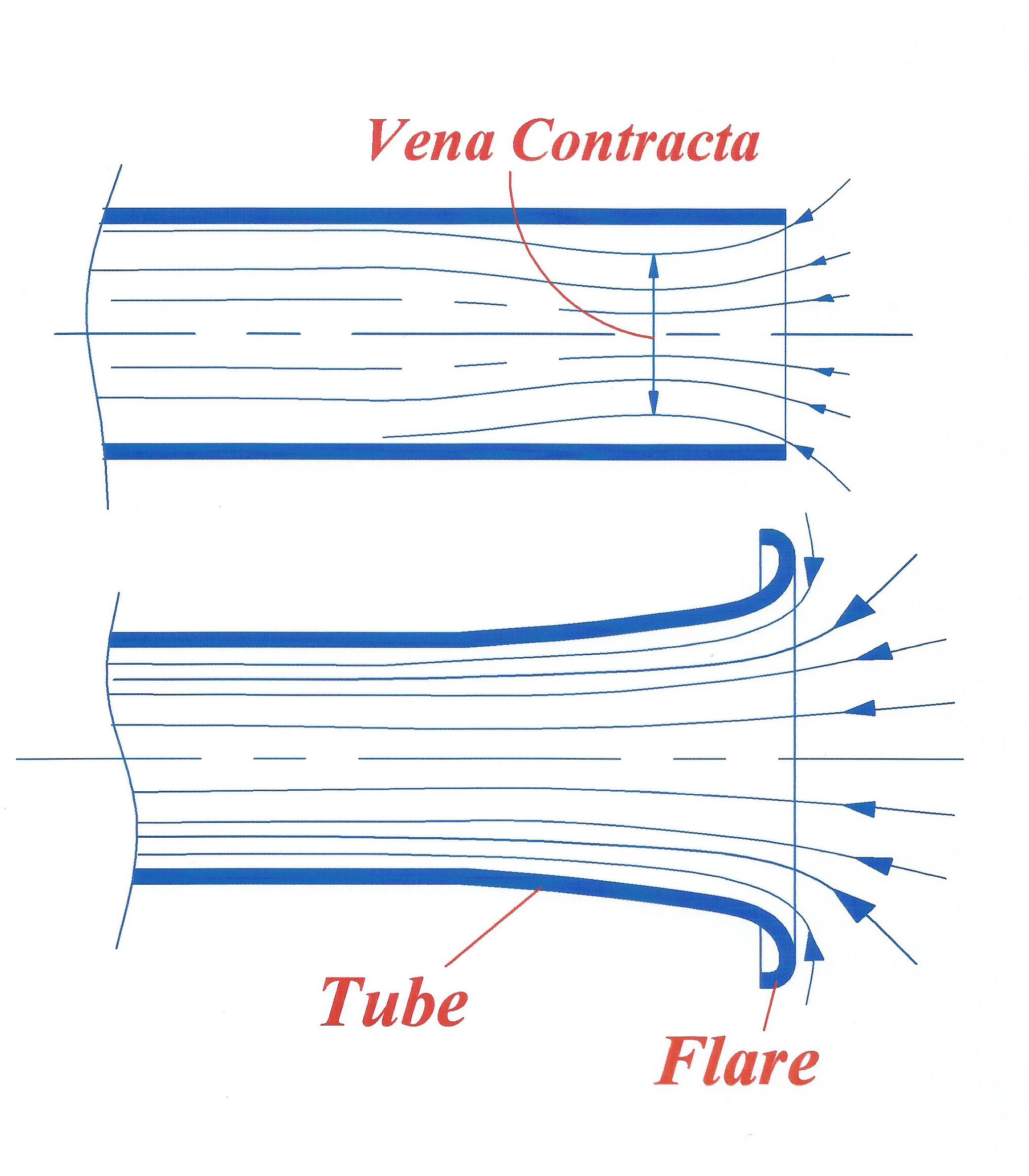 Fig. 1 - Profiles
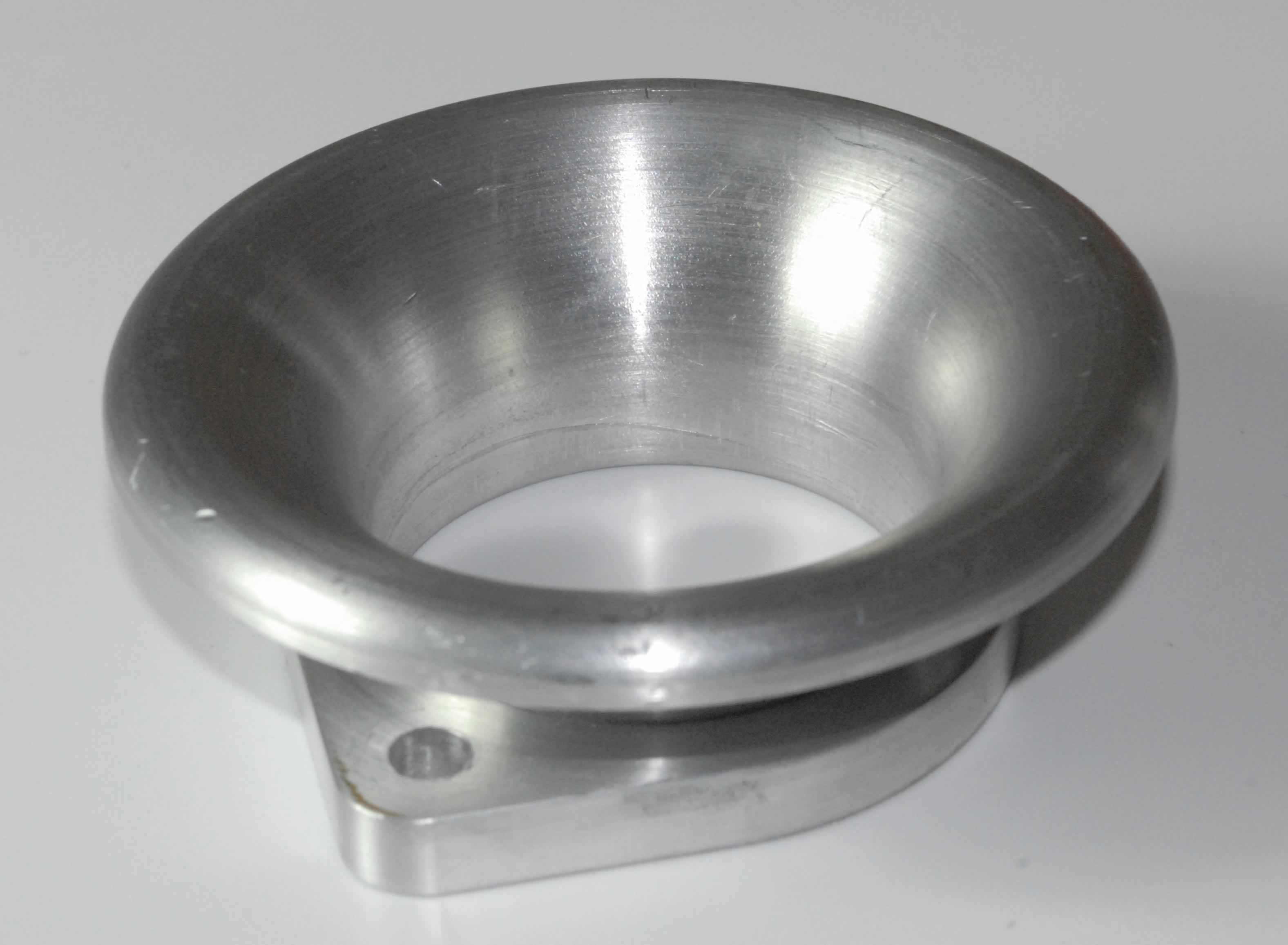 Fig. 2 - Typical bellmouth
Written by John Coxon
8255