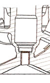
The Fuel Injector
 For those of you who have ever grappled with the art of carburettor ‘tuning’, the invention of the fuel injector must have come as something of a huge relief. The selection of choke sizes, main jets, emulsion tubes and air correction jets was all a bit fraught at times but once mastered and coupled with accelerator jets and something called ‘progression’, would seem to have guaranteed a job for life. Or so we thought. While the theory was always well understood it was only when we were able to view high-speed video that our true skills, or rather lack of them, was realised. Instead of the fine mist we all assumed, globules of fuel emanated from the carburettor spray bar and it was truly only down to the turbulence of the air in the intake port that mixed the fuel into any kind of combustible form.
Rather than just dribbling out under the action of the depression in the choke and whichever direction the air in the manifold happened to be pulsing at that instant, the invention of the electronically controlled fuel injector was a dream come true. Injecting the fuel at around 3 times that of atmospheric pressure and timing it to coincide with the positive pulse of air going into the engine, that same high-speed video now showed that the fuel droplet size was vastly improved. While engines generally gave little more outright power than before, the timing of the injection pulse enabled much better control of the engine and was to lead the way to a whole new range of possibilities.
Injectors are generally driven by ‘grounding’ the 12-volt electrical signal, and energising the coil within causing them to open, injecting the fuel at high pressure. Early versions were mainly of the ‘low impedance’ type. Typically having resistances between 1 to 4 ohms, once energised, the high currents involved generated lots of heat which was potentially damaging to the transistorised circuitry then in use. To limit this, injector drivers of the ‘peak and hold’ variety were devised. The battery voltage was applied until a pre-determined current was reached. At that point and once the injector was open, the current was then reduced by modulating the 12-volt source on and off very quickly for the remaining period of the injector opening. The high initial currents were designed to give improved injector response times while the subsequent reduction in current protected the switching transistors. When using these types of injectors it was therefore imperative to ensure that both the injector and driver characteristics were carefully matched achieving maximum injector response time but with minimum build-up of heat.
Later on, designs were introduced with a much higher impedance. These so called ‘high impedance’ injectors (usually between 12 –16 ohms) take the 12 volt feed directly without any form of current control and as such the associated drivers are generally referred to as the ‘saturation’ type. So long as the circuitry is designed for the task, a similar outcome can be achieved if a resistor is used in series with a low impedance injector but the advice must always be to check with your EMS supplier. In either case lower currents mean reduced injector response but the heat build up in the electronics should aid reliability.
While the mastery of the gentle art of tuning carburettors may no longer guarantee a job for life, the far wider scope enabled by it’s much younger sibling together with the advancement in modern electronics could possibly now do so.
Written by John Coxon.