The turbo ball bearing
 While the concept of the turbocharger has been around since 1926, the basic compressor/bearing housing/turbine hasn't changed that much in the past 50 years. Certainly compressor wheel aerodynamics have improved considerably and turbine technology has also changed quite a lot. But apart for the introduction of some variably geometry designs, outwardly most turbo units are still very similar to the ones I played with when I first started, many years ago. But if you look closer, particularly deep within the bearing housing assembly, things are beginning to change.
The issue here is so-called 'turbo lag'. Primarily a function of the lack of exhaust gas energy upon opening the throttle, and therefore an inherent issue with the technology, spool-up times (the cause of turbo lag) can still be reduced by minimising the rotating inertia of the wheels and attacking that perennial favourite of engineers - friction in the bearing assembly.
The traditional turbocharger bearing arrangement was described here in RET-Monitor a couple of months ago. A fully floating concept consisting of two journal bearings at either end of the shaft supported by an additional thrust bearing next to the compressor, the most dominant effect on the friction inside the rotating assembly is this thrust bearing.
Described by some turbo engineers as the 'Achilles heel' of the design, the thrust assembly generally comprises a fixed thrust bearing and a rotating ring. When oil is fed into the wide end of the tapered pad on the thrust bearing, the action of the rotation will drag it back into the narrow end, building up oil pressure to withstand the axial load. For most of the time, however, the direction of this axial load will vary; it very much depends on the pressures in and around the compressor and turbine wheels at any particular instant. The net axial load is then taken by one of the two opposing faces depending on its direction.
In hybrid turbos where bigger compressors are used, the compressor dominates and pulls the shaft towards it. If air restrictors are required (as in the case of some engine formulae) the situation is exacerbated and turbos need a lot of extra thrust capacity. For these units, 360º-type thrust bearings as opposed to the normal 270º versions are commonly found.
But since friction is the enemy of good low-speed transient response, the major push of late has been towards the use of ball bearings in the form of a cartridge replacing both the journal and thrust bearings. Consisting of a single sleeve containing a set of angular contact ball bearings at both ends, for a given radial load the friction difference between these and the standard plain journal is negligible. However, under axial loadings irrespective of direction, the traditional advantage of the ball bearing begins to show, allowing the central core of the turbo to spool up much quicker from low speed.
Although improved engine response results, the system has to be designed so that ideally it keeps the ball races in contact with both outer and inner races at all times and at both ends, irrespective of the direction of the axial thrust. Failure to ensure this could easily result in rapid failure at the speeds experienced, since rolling element bearings are notoriously poor in such circumstances.
And since turbochargers will become increasingly common in the coming years, reliability could be a major issue.
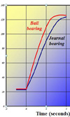
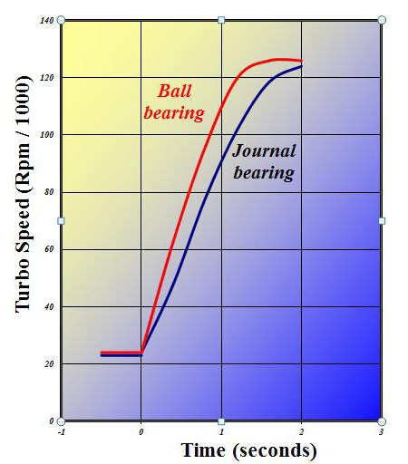
Fig. 1 - Comparison of spool-up times
Written by John Coxon
5473