The turbocharger bearing - a unique challenge?
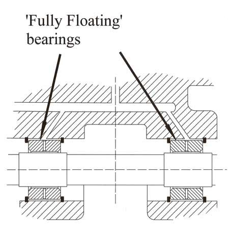
 Making a comeback from earlier times, the ball-race bearing system may be a preferred solution in some turbocharger applications, but for reasons of cost the more usual approach for the vast majority of units is still the fully floating design. Consisting essentially of two bushes, one at either end of the bearing housing through which the shaft passes, unusually these bushes themselves are allowed to rotate in their housing, creating in effect a 'bearing within a bearing'.
Manufactured from aluminium, or more likely some form of leaded bronze, these bearings are loosely restrained axially using a pair of 'snap' rings, one either side, and will therefore rotate along with the shaft according to the friction balance within the system. Simple in concept it may be, but the design of such a bearing is a lot more complex than you might think.
In the early days, when simple bushes were pressed into a housing, the compressor-turbine assembly became unstable at certain critical speeds. This would lead to excessive out-of-round movement of the shaft causing metal-to-metal contact between shaft and bearing, and the possibility of the compressor blade tips making contact with its housing. Increasing the shaft size and hence stiffness would move these critical speeds higher up the rev range, but at the same time increase rotating inertia and reduce spool-up times. Likewise, increasing the tip-to-compressor housing clearance prevented contact in this critical area but bearing durability was still compromised.
The not-so-obvious solution to all this was to allow the bush to rotate in its own housing and optimise the clearances, first between the shaft and bearing and then between bearing and its housing.

The original concept of the floating bearing was to minimise friction, for although frictional forces are low, at 100,000-150,000 rpm when friction is proportional to the square of the speed, this amounts to a significant amount of lost power. However, it was quickly found out that oil flowing between the bearing and its housing introduced an element of damping, preventing this metal-to-metal contact and improving durability. If the inner clearance between shaft and bearing is less than the outer clearance between bearing and housing then the sleeve will rotate at a fraction of that of the shaft speed, and the overall power consumed is reduced.
However, perhaps more important, an element of damping is introduced into the system, which will reduce the instability in the shaft. This enables the shaft to run freely through its critical speeds without the possibility of compressor wheel blade tips coming into contact with its housing. In practice, while it may be assumed that the bearing runs at about half that of the shaft speed, this apparently is rarely the case - a figure like 40% is more likely, but this depends on many factors. In one common design the figure is nearer 25%, while that of a slightly larger version is about 30%.

At typically between 0.0010 in and 0.0016 in (0.025-0.04mm), the inner clearance controls the load-carrying capacity of the shaft while the outer clearance, typically somewhere between 0.0026 in and 0.0034 in (0.066-0.086mm), controls the damping in the system. In production designs, actual clearances are generally selected based on running the bearing at the lowest possible speed when the durability of the bearing is at its highest.
Turbocharger bearings may to the layman appear to be simple but a considerable amount of engineering goes into their design and development.
Fig. 1 - Traditional turbocharger bearing layout
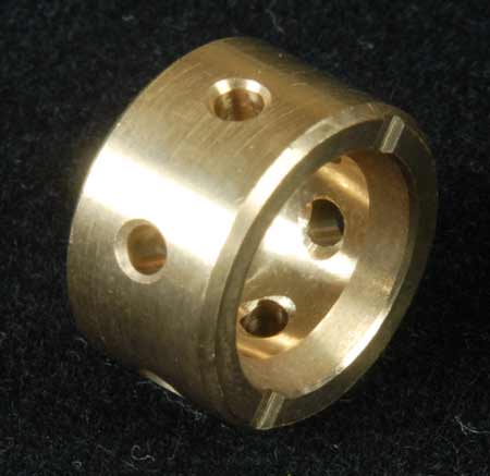
Fig. 2 - Typical turbocharger bearing
Written by John Coxon