Fuel flow measurement
 Controversial it may be, but the FIA's push to make Formula One more relevant to the roadcar world does seem to be having an impact. Take KERS for instance. Introduced in 2009, outlawed in 2010 and reintroduced for 2011, there must be hardly an OEM vehicle manufacturer anywhere who doesn't have some form of energy recovery programme of one form or another. Likewise, the rules for 2014 stipulating not the maximum amount of fuel to be used during a race (as has hitherto
been the norm) but the maximum fuel flow rate will no doubt have ramifications, since measuring gasoline fuel flow accurately onboard a vehicle has never been that easy.
In a test bed environment, where it is somewhat easier to control the environment, the instrument of choice was at one time the fuel balance. It was a system whereby the time taken for fuel (cooled to precisely the correct temperature) to empty a small chamber perched on a simple balance arrangement was measured, and average fuel consumption calculated, and it was both accurate and repeatable. Replaced by the coriolis device (see RET-Monitor, July 2011) having fewer moving parts, both these are bulky and therefore totally unsuited for in-vehicle installations.
For in-vehicle use, until recently perhaps, the main choice would have been a turbine flow meter. Consisting of a stainless steel, low-inertia turbine wheel or rotor within a non-magnetic housing, the speed of the turbine rotation is recorded by a magnetic pick-up attached to the side of the device. The AC voltage output generated is then proportional to the fluid flow rate, while the total number of pulses counted gives an indication of total mass flow. Since the rotor is immersed totally in the flow, turbine flow meters can exert a small but definite back pressure within the fluid, and as the flow needs to be laminar, great care is needed not to introduce turbulent flow immediately upstream.
Although highly reliable and accurate throughout most of their steady-state operating range, the mechanical nature of these devices and the inevitable friction within their bearings means that at low flows their accuracy can be impaired. In highly pulsating flows, such as those found in engine fuel systems, the inertia of the turbine wheel - however small - may lead to inaccuracies, and the fact that turbine wheels can jam and that the local pressure variations around the turbine blades under some conditions can create vapour lock does not truly recommend them to regular in-vehicle use.
However, the coming emphasis on fuel flow measurement in motorsport has encouraged the development of new types of flow meters, this time using ultrasonic technology. With no internal moving parts, and therefore no restrictions on the flow and its pulsating nature, the latest such devices can measure a wider range of flows with minimal impact on the pressures in the system.
Anodised aluminium for lightness and corrosion resistant to aggressive fuels (like ethanol), ultrasonic meters can measure the flow several thousand times per second, giving them the sensitivity to capture, so it is said, individual fuel injector flows at low engine speeds. Although not designed specifically for motorsport, such flow meters will have a much wider application where accurate fluid flow rates in hostile conditions are required.
Although it was possibly not their intention, the rule makers in Formula One may have accidentally spurred the way forward for many other categories to adopt fuel flow rate regulations and be relevant not just to the wider automotive world but to many other industries outside the sport.
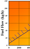
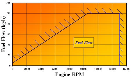
Fig. 1 - 2014 Formula One fuel flow envelope (revised 10/02/12 @ 15:10)
Written by John Coxon
3079