Tractive effort
 In recent RET-Monitor features we have considered several aspects of transmission design and engineering, each time with the implicit assumption that some means of gearing between the power unit and road wheels was a prerequisite feature.
Why should this be so, and how do we then determine what we need?
Essentially we seek to transform rotational motion and energy at the engine flywheel into linear motion and kinetic energy at the vehicle tyre contact patch. To do so we require a mechanical connection between the two. Consider something as simple as a slot car. This does not employ a gearbox, but a single pair of gears in mesh, one on the motor shaft and the other on the solid axle to which the driven wheels are rigidly attached. Depending upon the characteristics of the electric motor there will be a variation on the number of teeth on each gear - the gear ratio - but this will be fixed. Speed control is achieved completely by the hand held rheostat operating on the electric motor. We often call this hand controller the 'throttle' although the electric motor does not breath air to produce power as an internal combustion engine does.
In theory and with a sufficiently powerful motor there is no reason why this type of control cannot be used on a full size electric vehicle. Multiple ratio gearboxes are only required where the torque and power characteristics of the motor unit are such that, if geared directly through a fixed ratio to the road wheels, it cannot provide sufficient torque throughout its speed range to impart the required in line tractive effort throughout the vehicles operational speed range.
With an internal combustion engine this is almost universally the case. It's characteristic power curve rises to a peak from zero before falling sharply away again, which imparts a 'torque curve' that will also eventually fall with increasing speed . The phrase 'running out of steam' comes from an earlier era and a different type of powerplant with different characteristics again, but is still used to describe an internal combustion engine that can no longer sustain acceleration, or cope with an incline.
We use gearing to obtain twin objectives. On the one hand, it is intuitive that if we 'gear down' from the motor at a ratio of 2:1, then the geared axle will revolve at half engine speed. Our road speed will then depend upon the diameter of the driven tyres. At the same time, we will have increased the torque acting through the driven axle by a ratio of 2:1 when compared with the torque at the crankshaft of the engine. Conversely, when we 'gear up' at 2:1 we double speed and halve torque in comparison to the motor. On a typical car, we seldom find ourselves 'gearing up' except in the highest gear, which in a road car is referred to as an 'overdrive', and, in any case we put all of the torque through the gear train itself through one 'final drive' which reduces speed at something in the order of 3:1 and increases the torque to the driveshafts by 3:1.
In effect then, we are gearing down in all ratios between crankshaft and road wheel. Our lower gears, with the highest numerical ratio, give us the highest torque multiplication so that they can provide high tractive effort from a standing start, or to get out of a slow corner, but the vehicle will be speed limited in them. The mid range gears provide a balance between tractive effort and speed, whilst at the top of the range, we must sacrifice force for velocity.
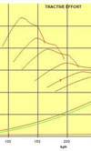
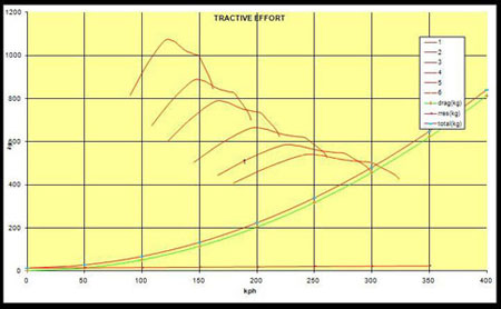
To visualise this process and the estimate what ratios we might require, we plot the tractive effort in each gear against the road speed. Tractive effort is obtained by multiplying engine torque and the overall gear ratio (gear and final drive), and dividing by tyre radius. Road speed in each gear is obtained from engine rotational speed using the same factors, and so in effect we obtain scaled versions of the engine torque curve in each gear, plotted against the road speed range that we obtain through the engine rev range in that gear. In the lower gears these will appear to be scaled up along the vertical axis (which represents Tractive Effort) and down along the horizontal, or speed axis. In effect they looked 'squashed' horizontally and stretched vertically. In the higher gears the opposite occurs. A typical series of tractive effort curves is shown in the accompanying illustration. This type of graph, when used with a conventional gear ratio chart, can tell us a great deal about performance, and this is something we will develop next time.
Fig. 1 - Traction effort graph.
Written by Peter Elleray
5789